GEOTECHNICAL ENGINEERING
BILLINGS
HomeSlopes & WallsActive/passive anchor design

Active & Passive Anchor Design in Billings

Evidence-based design. Reliable delivery.

LEARN MORE

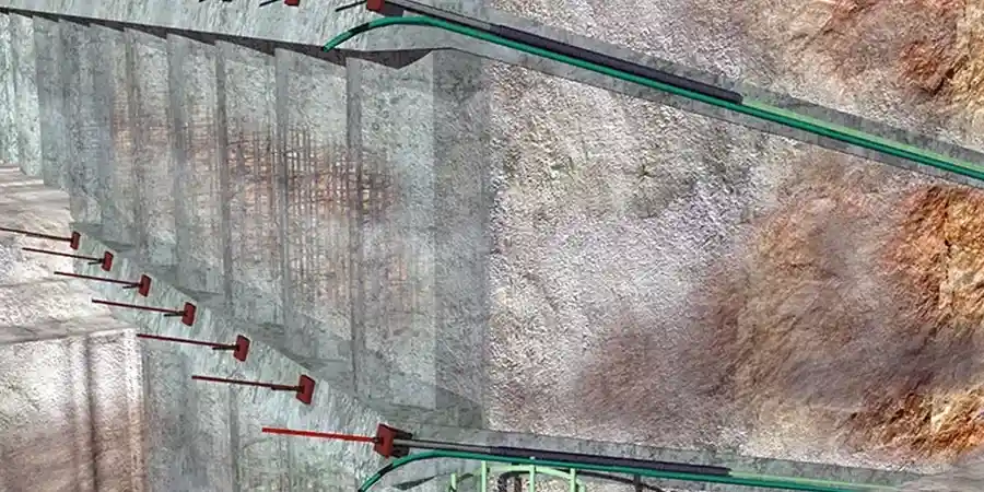
A contractor called us last fall about a deep excavation on the Rimrock Road corridor. The cut was nearly 30 feet into the Eagle Sandstone formation, and the shoring plan called for a tieback system that wouldn't hold. The original design missed a critical joint set in the rock mass. We re-engineered the active and passive anchor design using a bonded length that extended past the fractured zone, verifying capacity with a sacrificial test anchor on site. Billings geology isn't uniform across town. Beneath the topsoil, you find the Eagle Sandstone on the Rims, fractured shale in the South Hills, and deep alluvial gravels along the Yellowstone River floodplain. Each formation demands a different bond stress assumption. A design that works on the West End will fail downtown if you ignore the water table or the presence of cobbles in the gravel. We tie every anchor calculation to site-specific SPT drilling data and shear strength parameters from lab testing.

A 100 psi bond stress assumption that works in granite will cause a creep failure in the Cody Shale south of Billings.

Our service areas

Our approach and scope

The biggest mistake we see from out-of-state firms is using a generic bond stress of 100 psi for all Billings rock types. That number works for intact granite. It does not work for the thinly bedded, moisture-sensitive shale common in the Cody Formation south of town. A passive anchor installed without understanding the smear zone from rotary drilling will creep under sustained load and fail a proof test months later. Our anchor designs start with a detailed review of the drilling method. Air rotary, auger, and sonic drilling each produce a different borehole roughness and disturbance profile. For active anchors in alluvial gravel, we often specify a post-grouting stage to increase the effective bond diameter and compensate for collapse potential in the hole. Every anchor gets a unique bond length, not a template value. We also integrate the anchor response into the global stability model of the wall or slope, checking the compound failure surface that passes behind the bonded zone using Spencer's method. This catches the deep-seated failures that a simple free-body diagram will miss.
Active & Passive Anchor Design in Billings
Technical reference — Billings

Local geotechnical context

Anchoring in the gravel terraces near the Yellowstone River is a completely different problem from anchoring in the sandstone cliffs along Zimmerman Trail. The river gravels have high permeability. A water-filled borehole during grouting can wash out cement and create a neck in the anchor body. We've seen proof test failures where the load-displacement curve showed a sudden jump at 60% of the design load—classic sign of a grout column discontinuity. In the shale of the South Hills, the risk is time-dependent. Smectitic clay layers absorb water from the grout bleed and swell, reducing the radial effective stress against the borehole wall over weeks. A passive anchor that passes a 24-hour test may lose 30% of its capacity within a month if the grout mix wasn't formulated with a low water-cement ratio and a shrinkage-compensating admixture. We specify thixotropic grouts for these formations. The alluvial fans at the base of the Rims add another variable: undocumented fill with brick fragments and ash lenses from the old smelter days. An anchor installed through that material without a cased borehole will lose grout into the voids and fail to build pressure during stressing.

Need a geotechnical assessment?

Reply within 24h.

Email: contact@geotechnicalengineering.biz

Watch the video

Relevant standards

IBC 2021 (Chapter 18: Soils and Foundations), ASCE 7-22 (Minimum Design Loads for Buildings), PTI DC35.1-14 (Recommendations for Prestressed Rock and Soil Anchors), ASTM A416 (Low-Relaxation Seven-Wire Steel Strand), ASTM F432 (Standard Specification for Roof and Rock Bolts)

Technical data

ParameterTypical value
Design code for anchor loadsIBC 2021, ASCE 7-22
PTI RecommendationsDC35.1, DC35.2
Bond stress verification methodSacrificial test anchor to 133% DL
Maximum anchor test load for passive200% of design load
Creep criterion (sustained load)< 2 mm per log cycle of time
Typical unbonded length (tiebacks)10 ft minimum past failure plane
Grout specification for shale formationsThixotropic, w/c ratio ≤ 0.45
Corrosion protection for permanent anchorsClass I DCP per PTI DC35.1

Q&A

What is the difference between an active and a passive anchor?

An active anchor is post-tensioned to a design lock-off load immediately after installation. It actively applies a compressive force to the structure. A passive anchor, like a soil nail or rock dowel, only develops tension when the ground deforms. For a shoring wall that must limit deflection to less than 1 inch, you need active anchors. For stabilizing a cut slope where some movement is acceptable, passive nails are often more economical.

How much does an anchor design package cost for a project in Billings?

For a typical commercial excavation with 20 to 60 anchors, expect the design package to range from US$1,000 to US$3,780. The cost depends on the number of design sections, the complexity of the stratigraphy, and whether sacrificial anchor testing is required. A simple soil nail wall for a residential lot will fall on the lower end. A multi-row tieback system for a deep basement in the floodplain gravel will require more analysis and fall toward the upper end.

What corrosion protection grade do Billings projects typically require?

For temporary anchors with a service life under 24 months, a single barrier of neat cement grout is usually sufficient. For permanent anchors, especially in the alkaline soils common east of Billings or near de-icing salt runoff zones, we specify Class I double-corrosion protection per PTI DC35.1. This includes a corrugated plastic sheathing over the tendon and a grout-filled encapsulation over the full bonded length.

How do you verify the anchor capacity in the field?

We specify a sacrificial anchor test program before production drilling begins. A test anchor is installed at the most critical location and loaded to 133% of the design load for active anchors or 200% for passive anchors. The load-displacement curve is monitored for creep rate. If the creep rate exceeds 2 mm per log cycle of time, the bonded length is increased for the production anchors. Every production anchor then undergoes a proof test to 133% of design load.

Location and service area

We serve projects in Billings and surrounding areas.

View larger map